Forum Replies Created
-
AuthorPosts
-
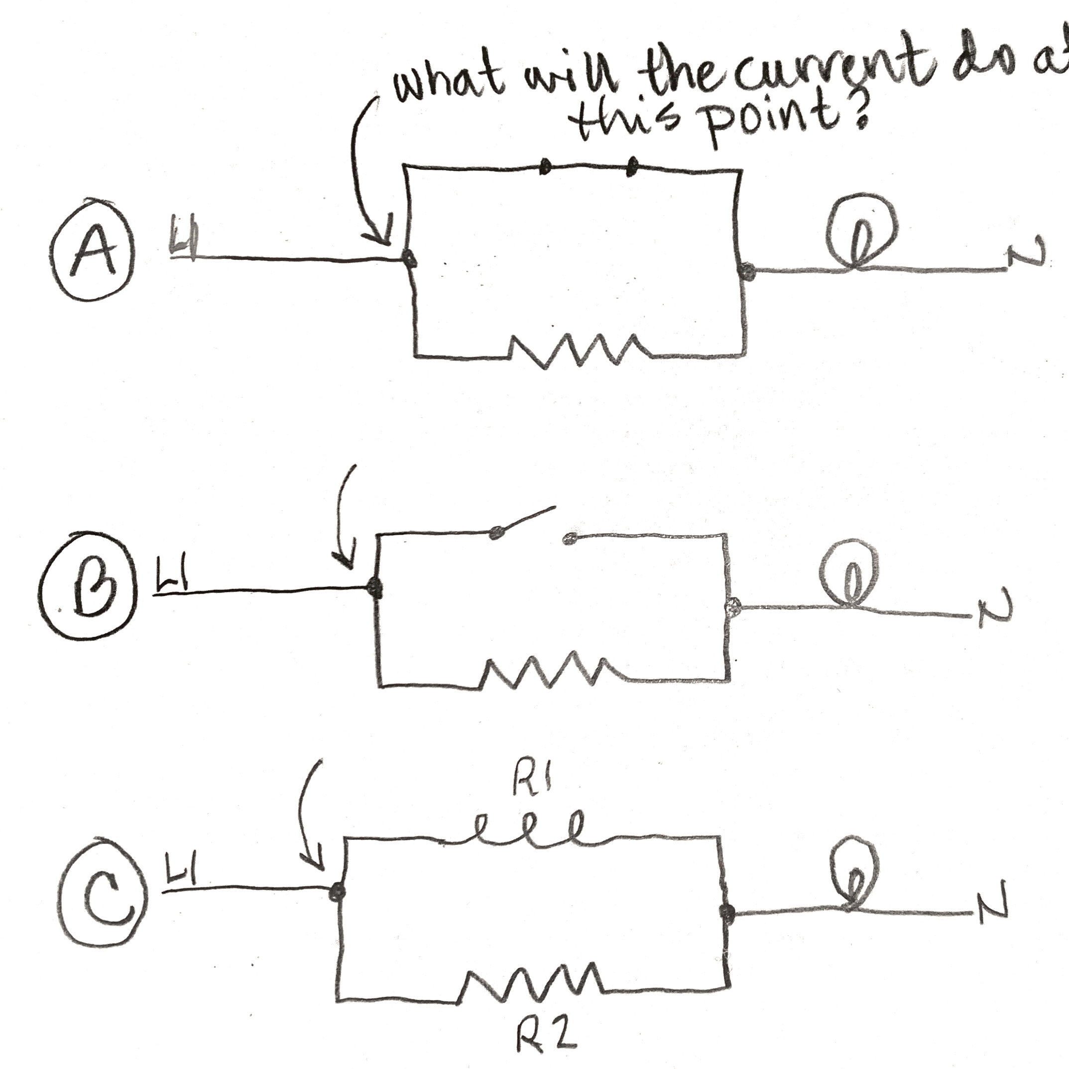
These are good questions, and it’s great to get a handle on this. Here are three scenarios. When the electrons get to the point where there are two possible paths, what will they do? In other words, tell me for each scenario (A, B, and C) how much current will flow through the different branches. For example, will 100% of the current flow through one or the other, or will it divide up in some way?
Are you able to answer this yet, or are you still unsure?
Correct – no current. If there’s no current flowing, even when we have some voltage present, that means there’s an ____ in the circuit (fill in the blank). (it’s good to be more specific than “bad”)
And, the measurements we give you tell you which side the ____ is on.
Voltage Drop:
Look in Unit 8. In the text before you get to the video, we define voltage drop and show you how to calculate it. Do you see it there?For Equivalent Resistance of parallel loads:
We cover this in the 3rd video of Unit 5, and in the text below that. If you don’t want to do the actual calculation, you can just tell us the rule of thumb, which we show you in that video.Let me know if you have follow-up questions!
This is a normal household circuit, so 120vac. You’d have L1 on one side of the bulb, and N on the other side. The bulb is good, but no voltage drop. We do measure 120vac wrt N from one side of the bulb.
Is current flowing?
Yes, you are overthinking this! The first choice answer you gave on the exam is correct.
At some point in the course we told you that when you see a component on a schematic, you should categorize it as a switch or a load. Loads do work (and therefore create voltage drop), but switches do not. If you know which category a fuse is in, then this answer is simple.
To me, they look like series circuits.
Correct. If the switch is open, current will flow through both the heater and the bulb, which are in series along a single circuit.
Why wouldn’t the heater operated when switch is closed?
In order for a load to do work, it must have power (voltage AND current). If the switch is closed, will the heater receive any current? If you aren’t sure, review the basic definition of a shunt (unit 1, unit 5).
can you also clarify why there is a shunt with a switch in this circuit. What role does it play?
The point of the questions at this point in the course is to teach basic electricity and circuits. It’s not a representation of an exact circuit that you might see in an appliance yet. But we discuss briefly how shunts might be used in circuits in the first video in Unit 5.
Does it have to do with resistance of the heater and a switch?
Yes – does a closed switch have any resistance?
I have not seen similar circuit in the book to get clear understanding. On the other hand the explanation of Shunts and Short in the on line presentation made more sense.
You don’t need to find exact replicas of circuits in the material to understand how they work, you just need to apply the basic concepts that you are learning.
I suggest you rewatch the videos in unit 5, and review the definitions in Unit 1. And, continue to answer/ask questions here!
The fact that a closed switch acts like a wire was discussed previously, for example in the first unit 4 video.
Then in unit 5 we teach the “Zen trick” to determine if loads are in parallel with each other or in series. Try that with both of the circuit drawings, A and B, and let me know what you find.
Hi Jay,
I’m not quite sure what you mean by a “shunt with control.” Do you mean the switch that is either open or closed? A closed switch acts like a wire, so with it closed, you have a shunt.
That’s how many circuits are designed – switches open or close to direct which loads are receiving current.
Hi Robert,
The clue is in the word “total”. What does that make you think of doing, mathematically?
Here’s one place where we show finding and using total resistance of two loads in series: the last video in Unit 3, starting around the 4 1/2 minute mark.
https://my.mastersamuraitech.com/module-3/basic-electricity-ohms-law/
We also mention total resistance of loads in series in the 3rd video in Unit 5: https://my.mastersamuraitech.com/module-3/basic-electricity-series-and-parallel-circuits/
Do you see how to do it?
Always glad to help!
Correct.
Do you have a way to print out the schematic? I would like to see you trace out how L1 can get to the LF hot indicator light.
Hi Tim,
It seems like you are looking at the wiring diagram, which is much more difficult to figure out. If you are looking at the “Hot Ind Lights” on the schematic diagram, it’s pretty simple to see the two wire colors coming in to the LF one. Let me know if that help you.
Well, yellow obviously is – you identified that as the wire on one side of the indicator light. We want to know the color of the wire that’s on the other side of the light. You just have to trace it towards the power supply to see its color.
One more question: if you have L1 on one side of an element, and current is flowing, can you still have L1 on the other side?
Does the explanation above not make sense in some way? We are pretty much spelling the answer out for you there.
Are you being thrown by the way the jumper wire is drawn? The whole wire is not shown on the schematic – just each end, where it ties into the other circuits. I’m trying to figure out how you think L1 could travel through a surface element on its way to the LF hot indicator light.
-
AuthorPosts